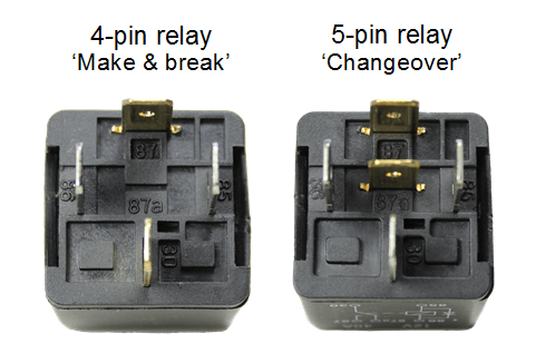
Terminal numbering convention
The terminal numberings found on a relay body are taken from DIN 72552 which is a German automotive industry standard that has been widely adopted and allocates a numeric code to various types of electrical terminals found in vehicles. The terminals on the outside of a 4 or 5 pin mini relay are marked with numbers as shown below:
|
Terminal/Pin number |
Connection |
| 85 | Coil |
| 86 | Coil |
| 87 | Normally Open (NO) |
| 87a | Normally Closed (NC) – not present on 4 pin relays |
| 30 | Common connection to NO & NC terminals |
According to DIN 72552 the coil should be fed with +12V to terminal 86 and grounded via terminal 85, however in practice it makes no difference which way around they are wired, unless you are using a relay with an integrated diode (see more info on diodes below).
Tip: you can use a changeover relay in place of a make & break relay by just leaving either the NO or NC terminal disconnected (depending on whether you want the circuit to be made or broken when you energise the relay).
Terminal layouts
The automotive ISO mini relays we have been looking at above are typically available in two types of pin layout designated Type A and Type B layouts. These layouts are shown on the two 5-pin relays below (pin 87a not present on 4 pin relays):
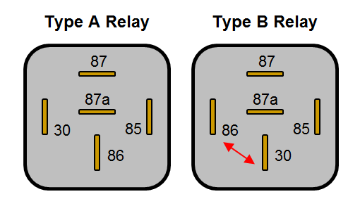
You will notice that on the Type B layout pins 86 and 30 are swapped over compared with the Type A layout. The Type B layout is arguably easier to work with as the connected terminals are in-line, making the wiring easier to visualise. If you need to replace a relay make sure you use one with the same terminal layout as it is easy to overlook if you’re not aware of the difference.
Terminal sizes
The terminal widths used on 4 and 5 pin relays are almost always 6.3mm wide, however some more specialist relays can have terminal widths of 2.8mm, 4.8mm and 9.5mm. The 9.5mm wide terminals tend to be used for higher power applications (such as for starter motor solenoid activation) and the smaller terminals tend to be used for electronics signalling where only very low currents are required. All widths will be compatible with the standard female blade crimp terminals of the corresponding sizes.
Relay body markings
Relays can look very similar from the outside so they normally have the circuit schematic, voltage rating, current rating and terminal numbers marked on the body to identify them.
- Circuit schematic
This shows the basic internal circuits (including any diodes, resistors etc.) and terminal layout to assist wiring.
- Voltage rating
The operating voltage of the coil and high current circuits. Typically 12V for passenger vehicles and small craft but also available in 6V for older vehicles and 24V for commercial applications (both auto and marine).
- Current rating
This is the current carrying capacity of the high current circuit(s) and is normally between 25A and 40A, however it is sometimes shown as a dual rating on changeover relays e.g. 30/40A. In the case of dual ratings the normally closed circuit is the lower of the two, so 30A/40A, NC/NO for the example given. The current draw of the coil is not normally shown but is typically 150-200 mA with a corresponding coil resistance of around 80-60 W.
Tip: Knowing the coil resistance is useful when testing the relay for a fault with a multi-meter. A very high resistance or open circuit reading can indicate a damaged coil.
- Terminal numbering
The numbers 85, 86, 30, 87 & 87a (or other numbers for different relay configurations) are normally moulded into the plastic next to each pin and also shown on the circuit schematic.
Relay configurations and types
In addition to the basic make & break and changeover configurations above, ISO relays are available in a number of other common configurations which are described in the table below:
| Configuration |
Circuit schematic * |
Description |
| Make & break relay | 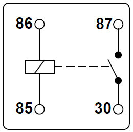 |
The most simple form of relay. The circuit between terminals 30 and 87 is made on energisation of the relay and broken on de-energisation, known as NO (or vice-versa for a NC relay). |
| Changeover relay | 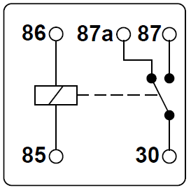 |
Two circuits (terminals 87 and 87a ) have a common terminal (30). When the relay is at rest 87a is connected to 30, and when the relay is energised 87 becomes connected to 30 (but never both at the same time). |
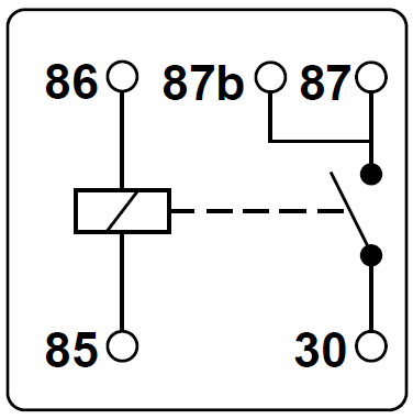
| Relay with double output |
|
Terminal 87 is linked to pin number 87b, giving double outputs from the single NO contact. |
|
Relay with dual contacts |
|
The armature contacts both terminal 87 and (in this case) 87b at the same time when the coil is energised, creating a dual NO output |
|
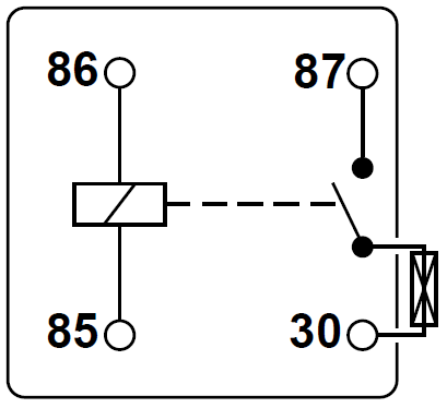
Relay with integrated fuse |
|
A blade or ceramic fuse is connected between terminal 30 and the NO contact, providing built-in protection for the high current circuit. The fuse is normally mounted in a holder moulded as part of the relay body so it can be replaced if it blows. |
|
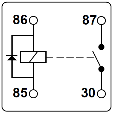
Relay with diode across the coil |
|
When voltage is removed from terminals 85/86 and the coil is de-energised, the magnetic field that has been created around the coil collapses rapidly. This collapse causes a voltage across the coil in the opposite direction to the voltage that created it (+12V), and since the collapse is so rapid the voltages generated can be in the order of several hundred volts (although very low current). These high voltages can damage sensitive electronic devices upstream of the +12V coil supply side, such as control modules in alarm systems, and since it’s common to take low current alarm output signals to energise relay coils, equipment damage is a real risk. Using a relay with a diode across the coil can prevent this damage by absorbing the high voltage spikes and dissipating them within the coil/diode circuit (this is known as a blocking or quenching diode). The diode will always be installed in the relay with the stripe on the diode body facing towards terminal 86 (reverse biased) and it is important that +12V is connectedthis terminal, not 85 (as per the DIN standard) or the diode could be damaged. |
|
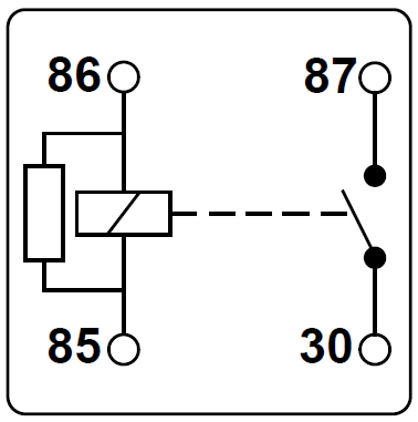
Relay with resistor across the coil |
|
A high value resistor performs a similar function to that of the diode in the previous configuration by absorbing the high voltage spikes created by the collapsed magnetic field on de-energisation of the coil. The disadvantage of a resistor is that it allows a small current to flow in normal operation of the relay (unlike a diode) and is not quite as effective as a diode in suppressing voltage spikes, but it is less susceptible to accidental damage because resistors are not sensitive to polarity (i.e. it doesn’t matter whether +12V is connected to terminal 85 or 86). |

* All schematics shown with the relay at rest (de-energised)